Sense Boards
Hardware » Sense Boards
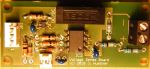 Voltage Sense Board
 Voltage Sense Board Schematic
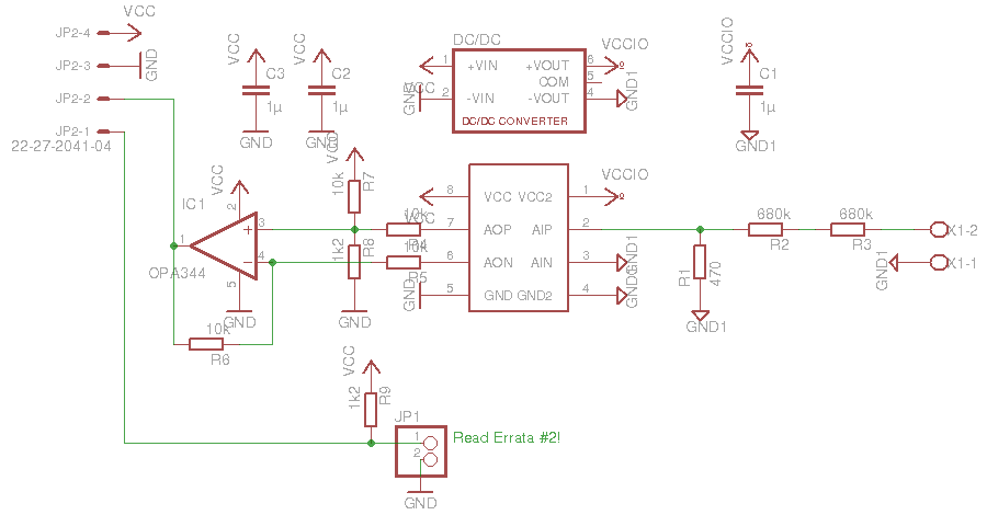
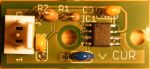 Current Sense Board
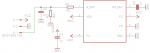 Current Sense Board Schematic


3 sensing boards provide the inverter with values for the DC link voltage, heat sink temperature and two phase currents.
Voltage Sense Board
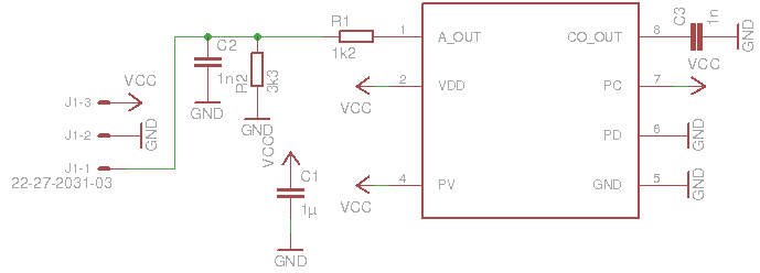
The voltage sense board uses an Si8920 analog isolator. It converts a voltage of 200mV on the primary (right side on schematic) into around 3V on the secondary side. Since the isolators output is differential we need an opamp circuit to make it single-ended.
The board also provides the connection for the heatsink temperature sensors.
Current Sense Board
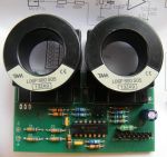
The current sense board used a Melexis MLX91205 magnetic field sensor. It outputs 2.5V at 0 T and swings between 0.25V and 4.75V at +/-25mT. With a simple resistive divider that is scaled to the 3.3V range. The board is supposed to be mounted directly on the phase output cable or bus bar. The correlation between the phase current and the output swing varies with the distance between the conductor and the chip. With no further spacers the range is about 800A on cable. A busbar needs an additional isolation layer.
Make sure to place the two sense board far apart from each other and any other high current conductor to avoid cross talk.
Sensor Board
Go here for information about the legacy Tamura/LEM sensor boards.